flowchart TD
    GUI[GUI Design E-R Model] -->|Physical Model| DB1(Created Tables)
    DB2(Created Tables) --> |Reverse Engineer| Diagram[E-R Model]
16 Entity Relationship (ER) modelling
16.1 Entity Relationship modeling Basics
Entity Relationship (ER) modeling or diagramming is introduce by Peter Chen Chen (1976) in 1976. ER-Models consists of three parts
- Entity
- Relations
- Attributes
Entities are basically tables in databases, like Student, Employee, Customer and Invoices. Relations shows the connections between entities. For example, a Customer has invoices. Attributes shows the values an entity have: For example, Customer entity will have name and phone.
Original syntax is called Chen notation. Below is an figure from the original article Chen (1976).
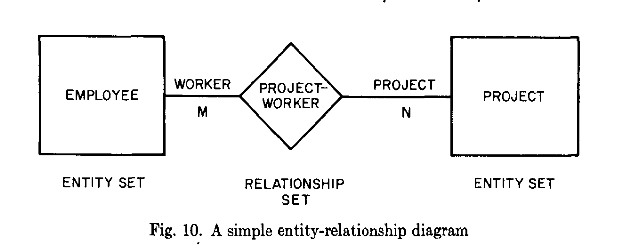
The diagramming syntax is evolved by then but the basics stayed same.
16.2 How it works
ER-modelling work two ways, as below figure shows. First way, we could create diagrams then database tables. Second way, we could reverse engineer our diagrams from our database tables.
16.3 ER Modelling tools
For first way, there are a lot of tools exits. Examples:
See following video for how one tool works. LucidChart Tutorial: How to Create an ERD
16.4 ER model reverse engineering tools
Second way of working, reverse engineering existing database is more common. We reverse engineer an already existing database and get ER Diagram of it. For example, DBeaver has ER Diagrams.
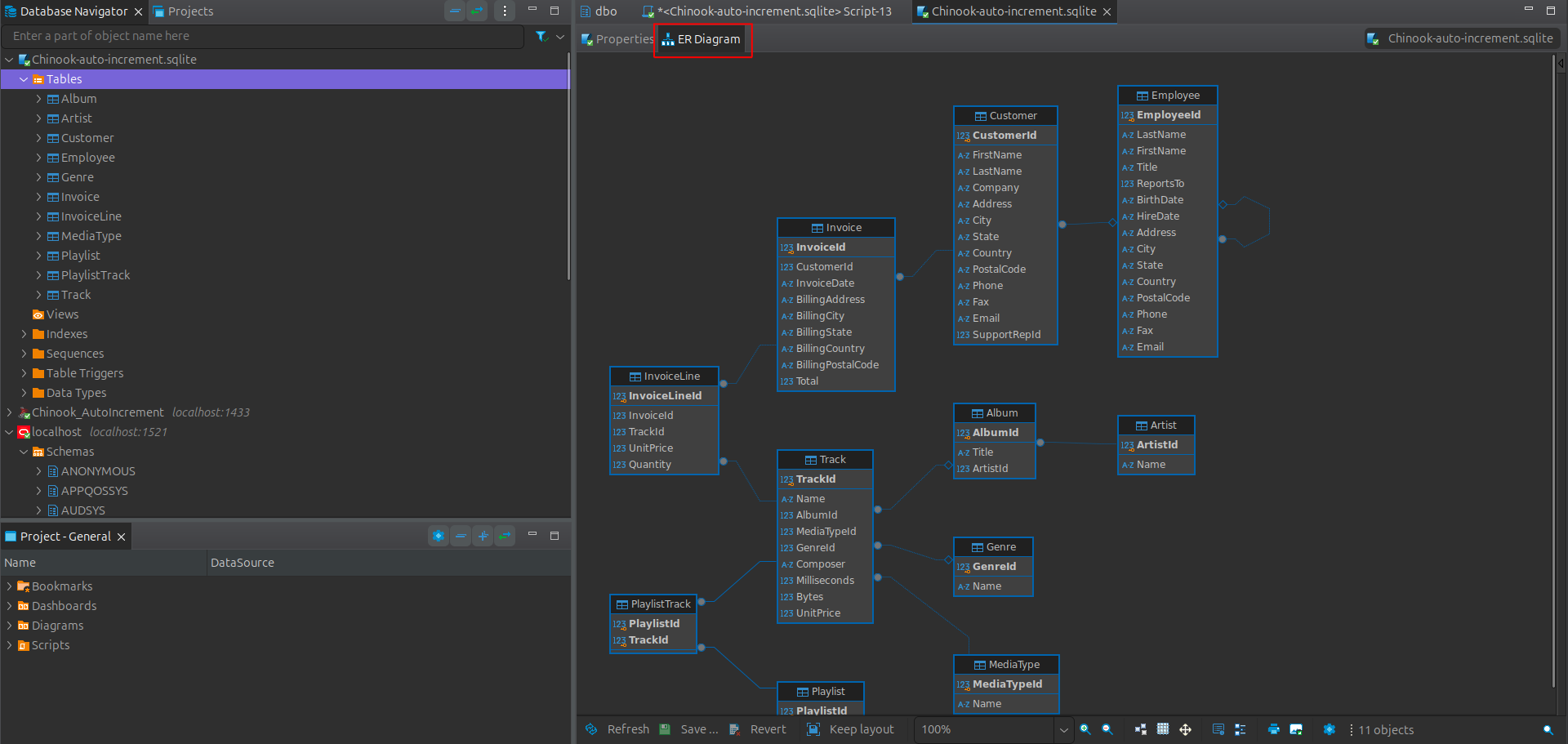
- Open a connection
- select tables
- in the opened window, select ER Diagram tab
Reading ER diagrams is useful skill to have since it allows you to more easily understand existing database structure.
See oracle sample HR and OE example in their documentation
Oracle SQL Developer has its own reverse engineering tools for oracle database. TODO add links.
Another tool for this purpose is Schema Spy.